Studyexperiment
Kinetic Planes — After Abraham Palatnik
Flexible elements, oscillating movement and improvised mechanical connections
Inspired by Abraham Palatnik's C-15, this study uses a reused wooden frame, an OS20 construction grid, nylon rods and a 28BYJ-48 stepper motor to investigate how a simple reversing rotation can produce flexible, layered motion—and how improvised connections can become reusable parametric parts.
From C-15 to a physical question
This experiment began with *Abraham Palatnik's Objeto Cinético C-15*** and a question about how simple moving elements can create the perception of changing planes. The C-15 reference already documents the artwork and its place in this research; this entry is about what happened when I tried to explore some of its principles with the materials and mechanisms available in my studio.
I was not trying to reproduce C-15. I wanted to investigate how a small number of moving, flexible elements could make a composition change over time—and what might happen if the planes were allowed to bend rather than remain rigid.


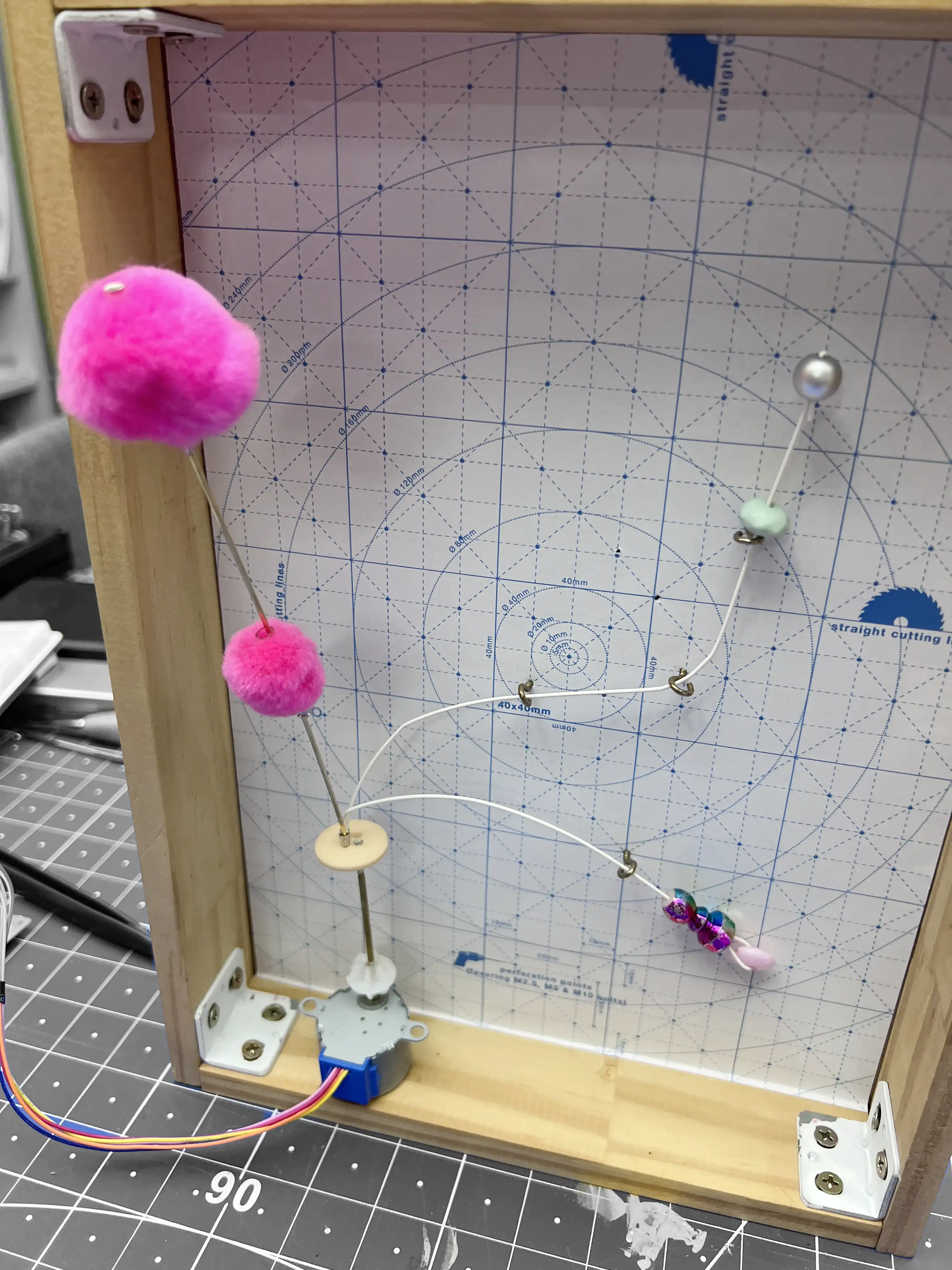
Building a temporary kinetic canvas
I started with a wooden frame I already had. Instead of making a new enclosure, I closed the back with cardboard and marked an OS20 grid with 20 × 20 mm spacing, using the OpenStructures-inspired connection logic I have been developing for Artificial Emotion.
The grid gave me a reference for positioning and rearranging small attachment points. I added screw eyes as guides and anchors, and worked with thin, flexible nylon rods, approximately Ø1.5 mm. Nylon was appealing because of its flexibility and the possibility of less friction at contact points, although I did not measure friction in this test.
The wooden frame and cardboard were not intended as a finished construction. They were a quick, adjustable surface for testing relationships between fixed points, flexible lines and moving elements.
This setup gave me a way to investigate planar composition without committing too early to a final arrangement or fabrication method.
One motor, two directions
For this study I used a 28BYJ-48 geared stepper motor controlled by an Arduino Uno. The programmed motion was continuous and reciprocal: 360° in one direction, followed by 360° in the other, at approximately 4 RPM.
This is a servo-like behaviour implemented with a stepper motor, not a conventional hobby servo. Rather than commanding an absolute position with feedback, I controlled a sequence of steps in alternating directions. In this test, the motor's repetitive motion became a simple way to observe the changing relationships between elements.
The slow, reversing rotation was especially useful here. The experiment did not need high speed; it needed movement that I could repeat, watch and modify while changing the mechanical arrangement.
Improvised mechanical connections
Getting from the motor shaft to the moving composition was harder than writing the motion sequence.
I experimented with a four-hole sewing button and a hollow brass tube with a nominal outside diameter of 2 mm. The tube was not a solid metal rod. Connecting it to the 28BYJ-48's approximately 5 mm, double-flat output shaft was awkward: these are two very different mechanical interfaces.
I improvised an intermediate connection using a small accessory originally intended for bicycle decoration, together with hot glue. Hot glue is not my favourite fastening method, but it is extremely useful in a dirty prototype: it lets me test an arrangement immediately, without first solving every fabrication detail.
That temporary connection was enough to continue investigating the movement. It also revealed a recurring problem: every new experiment with the 28BYJ-48 demands another decision about how to connect something to its shaft.
The improvisation worked as a way to ask the next, more specific design question. Could I make a compact, repeatable and removable connection between the motor's double-flat shaft and a 2 mm tube?
From improvisation to parametric fabrication
I moved from the hot-glued connection to parametric 3D-printed interfaces in OpenSCAD. Two parts emerged from this work: a shaft coupler and a mounting flange.
The shaft coupler accepts the 28BYJ-48's nominal 5 mm double-flat profile on one side and a Ø2 mm output on the other. Its output diameter is adjustable in the OpenSCAD source. Instead of relying on hot glue, the design uses M2 set screws and captive M2 nuts. The nuts can be inserted into open pockets after printing, without pausing the printer. On the motor side, the screw is oriented to press against one of the shaft's flat faces.
The flange preserves that motor-side connection but replaces the 2 mm output with a circular mounting face. It has four M2 clearance holes, making it possible to attach disks, arms or other experimental elements without redesigning the motor interface each time.
Both parts were printed and physically tested. These are working iterations rather than final standardized components: their fit, durability and repeatability will continue to inform later versions.
What interests me is the transition from an improvised, one-off solution to a small reusable system. The motor stays the same, while the geometry on the other side of the connection can change with the study.
Parametric fabrication files
The OpenSCAD sources and printable STL models are kept with this experiment, in homages/c-15-homage/ at the root of the repository.
Shaft coupler — V3
Mounting flange — V1
What this study opens up
I liked the movement that emerged from this first arrangement. The combination of a slow reversing motor and flexible nylon elements suggests a wider investigation with branches, overlapping elements and additional planes. What began as a study after Palatnik is becoming a question of its own: how can the flexibility of a material contribute to a mechanical composition rather than simply follow it?
The study also exposed a practical obstacle. I still do not have a sufficiently quick way to prepare a 28BYJ-48 motor for a new experiment. This time I built the control electronics around an Arduino Uno, but repeating that setup each time interrupts the process of testing motion.
The next step is therefore partly electronic: develop a ready-to-use motor control setup for the Artificial Emotion kinetic studies, so I can move from an idea to a physical test without rebuilding the circuit.
At the same time, the coupler and flange suggest a growing vocabulary of interchangeable motor interfaces. They do not solve every connection, but they make the next experiment easier to begin.
The most useful outcome of this study may be precisely this combination: a new direction for flexible kinetic planes, and a more repeatable way of making them move.