Studyexperiment
Artificial Emotion Controller — Designing a Dedicated PCB
From repeatedly assembled motor circuits to a modular controller for kinetic studies
Designing the first dedicated Artificial Emotion controller in KiCad, a manually assembled, through-hole PCB built around an ESP32-S3 SuperMini, a ULN2003A driver, one 28BYJ-48 stepper motor and configurable sensor connections. The aim is to make the electronics easier to reuse so each new kinetic experiment can begin with movement rather than wiring.
Question
How can the electronics for an Artificial Emotion kinetic experiment become a reusable starting point rather than something I have to rebuild each time?
The small 28BYJ-48 stepper motor has become a recurring part of my kinetic studies. It is useful for trying out slow rotations, reversals and mechanical linkages, but the electrical setup still takes time: a microcontroller, a motor driver, power connections and whatever sensors a particular experiment requires.
I wanted to turn that repeated preparation into a dedicated object: one controller for one motor, ready to be integrated into different mechanisms.
From a circuit to a board
The first version is designed around an ESP32-S3 SuperMini and a ULN2003A transistor-array driver for a single 5V 28BYJ-48 unipolar stepper motor. The goal is not to make a universal motor controller, but to establish a compact and consistent electronic foundation for this specific family of experiments.
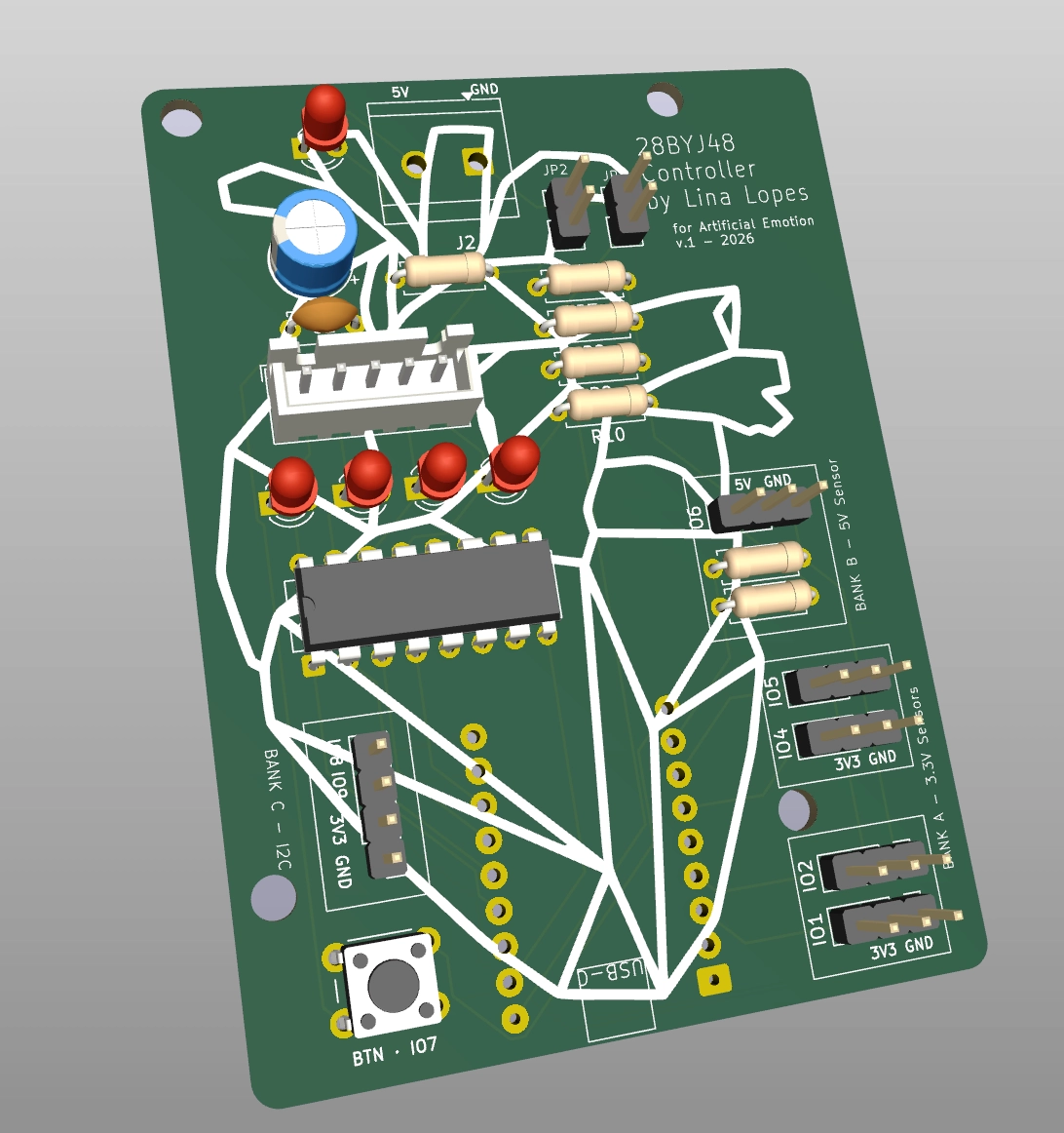
I developed the schematic and PCB layout in KiCad 10. Instead of treating the circuit only as a set of electrical relationships, I also had to decide where each connector would sit, how traces would travel across the board and how someone would interact with the physical object while testing a mechanism.
Organizing the connections
The controller groups its interfaces according to the kinds of experiments I expect to make:
- Bank A: four three-pin connections for 3.3V-compatible analog or digital sensors, using GPIO1, GPIO2, GPIO4 and GPIO5.
- Bank B: one 5V-powered sensor connection, with its signal routed to GPIO6 through a 10kΩ / 15kΩ voltage divider for compatible 0–5V signals.
- Bank C: a 3.3V I²C connector, with SDA on GPIO8 and SCL on GPIO9.
- USER button: a tactile input on GPIO7, connected to ground and intended to use the internal pull-up.
- Motor: four control signals on GPIO10–GPIO13, routed through the ULN2003A to the motor connector.
A significant design decision was to give four connections to 3.3V sensors and only one to a 5V sensor. This better reflects the likely needs of the experiments, while retaining a way to connect a compatible 5V-output device.
The board also includes four optional LEDs to indicate motor-phase activation. They are observation tools, not required for driving the motor.
Illustrated connection diagram
An illustrated wiring diagram will show the ESP32-S3 at the center, with visible connections to sensor banks, the USER button, ULN2003A, 28BYJ-48 motor and power distribution.
Power as a design decision
This revision uses an external regulated 5V supply through a screw terminal. Two removable jumpers separate the supply paths: JP1 connects external power to the ESP32, while JP2 connects it to the motor rail.
The motor supply includes a 100µF electrolytic capacitor and a 100nF ceramic capacitor. A separate LED indicates the presence of external 5V power.
I deliberately left battery-powered operation out of this version. The ESP32-S3 SuperMini may provide battery connection pads, but a complete battery-powered motor controller also needs a considered power architecture. For now, external power keeps the first fabrication focused on motor control, connections and assembly.
There is also an important limitation to verify during testing: USB-C power and external 5V should not be combined with JP1 closed unless the power-path behavior has been checked.
Designing for assembly and observation
Most parts are through-hole components: the DIP-16 ULN2003A, resistors, LEDs, capacitors, connectors and button. This is a deliberate prototyping choice. A board I can populate, inspect, repair and modify myself is useful while the design is still evolving.
The PCB is not only a technical substrate. Its placement of components, traces and silkscreen also begins to establish a visual identity for the controller as one of the physical objects of Artificial Emotion.
The KiCad 3D view offers another way to consider that transition: from an electrical schematic to a designed object with height, interfaces and a physical presence.
Observation
At this stage, the result is a designed PCB, not yet a fabricated and electrically validated controller. The schematic and layout define an initial architecture, and the shift from breadboard-style assemblies to a dedicated PCB makes the repeated connections much more explicit.
The process also revealed an important distinction between two kinds of drawings. A KiCad schematic is essential for maintaining electrical consistency, but it is not necessarily the clearest way to communicate the controller to someone visiting the research website. An illustrated, pin-by-pin Excalidraw connection diagram can show those relationships as a readable map without replacing the actual engineering files.
The PCB also incorporates Ø3 mm mounting holes positioned on a 20 × 20 mm grid, following the modular construction system being developed for Artificial Emotion. This allows the controller to be mechanically integrated into kinetic modules, such as MauMau, with the possibility of mounting it directly onto the side panels. The intention is for the electronics to become part of the same modular assembly language as the mechanisms they control.
Next
The next step is to review the final electrical and physical details before ordering a board: connector pin order, power behavior, silkscreen, footprints, ERC/DRC results and fabrication outputs.
After assembly, I want to test the controller with a 28BYJ-48 and different sensor configurations, paying attention not just to whether the motor turns, but to how quickly the board lets me begin a new kinetic experiment.
Project files: Artificial Emotion Controller v1 on GitHub