Studyexperiment
Artificial Emotion Controller — First Assembly and Tests
A working PCB, a corrected silkscreen, and a button that turns motor control into a physical interface
The first assembled Artificial Emotion Controller moved beyond circuit validation to reveal something more interesting - a single user button can become a compact physical interface for exploring different kinetic behaviours. Initial tests also exposed reversed 5V and GND silkscreen labels at the external power input, a small but consequential usability error now corrected in the design.
Question
What changes when a dedicated motor controller becomes a physical object that can be assembled, powered, programmed and handled?
And can one small button make a stepper motor's different movements immediately available for experimentation, without editing or uploading code each time?

Setup — The first board
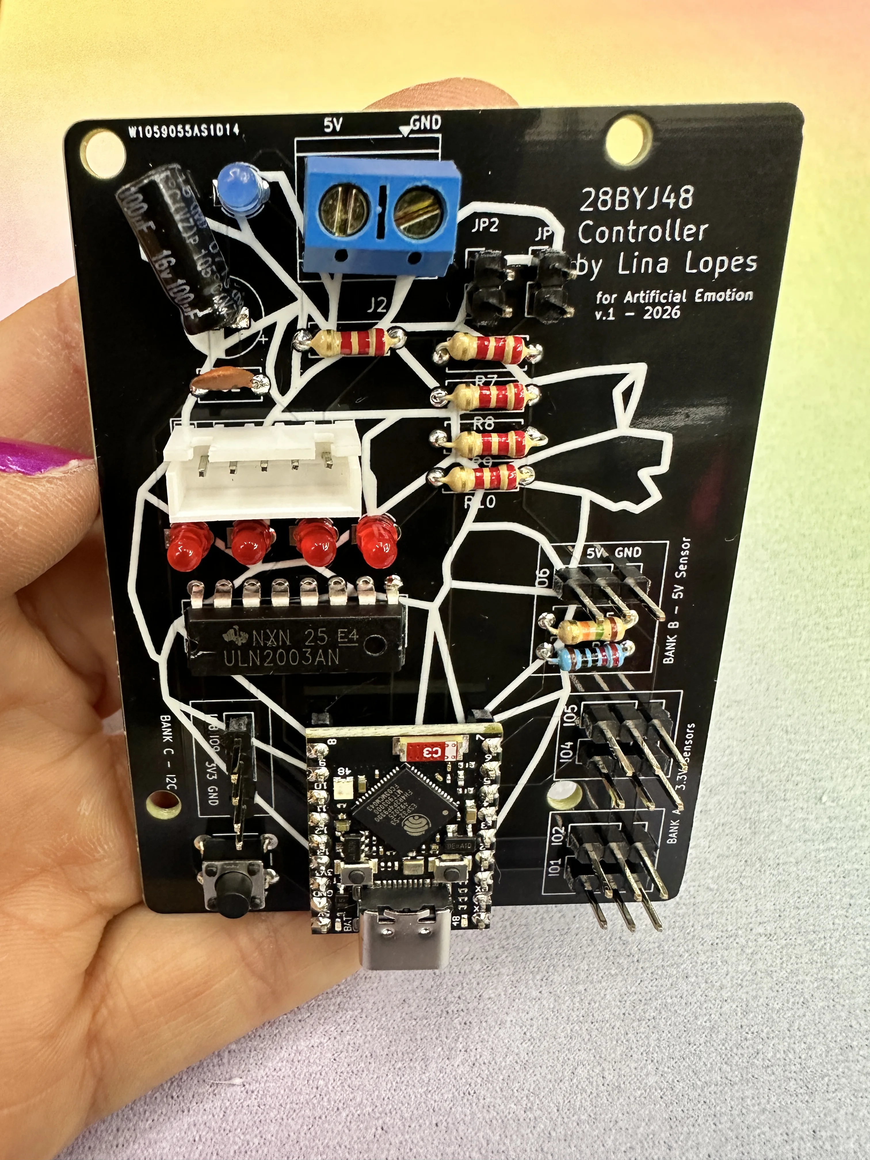
The first batch of ten Artificial Emotion Controller v1 PCBs arrived. I had enough components to assemble one complete board, so I started with a single controller before building the remaining nine.
The board is based on an ESP32-S3 SuperMini, a ULN2003A driver and one 5V 28BYJ-48 stepper motor. It also includes connections for future sensors, motor-phase indicator LEDs, a user button, and two jumpers for routing external power.
The original aim was practical: to stop rebuilding the same motor circuit for each kinetic study. A dedicated PCB could make a motor ready to use, while leaving room for different mechanisms and experiments around it.
For the first tests, I connected the ESP32-S3 to a computer over USB for programming and communication through the Arduino Serial Monitor. The motor received its own external regulated 5V supply, with JP2 closed to connect the motor supply and JP1 open so the ESP32 remained powered over USB.
A small marking error with a large effect
The first tests were confusing. The firmware uploaded, the controller communicated with the computer, and the user button responded, yet the motor did not move as expected.
I checked the power path with a multimeter: the incoming 5V, the jumpers and the 5V pin at the motor connector. Eventually, the source of the power-connection confusion became clear. On the external power input, the silkscreen labels for 5V and GND were reversed.
The connections defined by the circuit were correct; the labels printed on the board were not. Correcting how I connected the external power supply allowed the motor to receive 5V and the movement tests to proceed.
This is a small error in a drawing, but not a small error for the person using the board. Silkscreen is part of the interface: it tells someone where to put a wire and what to expect from a connector. A misleading label can make a functional circuit appear broken and, in the case of power, can create a risk of incorrect connections.
I have already corrected the 5V/GND labeling in the KiCad design for subsequent fabrication. For the first batch of ten black PCBs, I plan to cover the incorrect white markings with black paint and mark the correct polarity clearly. This is a practical repair to the physical interface, not an electrical redesign.
The unexpected discovery — One button, several behaviours
The most interesting result of this first assembly was not simply seeing the 28BYJ-48 turn. It was discovering what the USER button could do.
We had included a tactile button on the board, connected to GPIO7. Once the hardware was working, it became a way to explore motor behaviours directly, without returning to the laptop, changing constants, or uploading another sketch.
The current Arduino firmware offers three modes at 2 RPM:
- Continuous clockwise rotation — the default when the controller starts.
- Continuous counterclockwise rotation — the same speed in the opposite direction.
- Alternating movement — approximately 360° clockwise followed by 360° counterclockwise, repeating continuously.
A short press of the USER button advances to the next mode, cycling through all three. The Serial Monitor can also select the modes using 1, 2, or 3, while 0 stops and releases the motor and ? displays the menu.
The initial tests also revealed that the software's clockwise and counterclockwise definitions were opposite to the motor's observed direction. I reversed the direction mapping in the firmware so that the labels correspond to the physical movement.
The distinction matters. What began as a simple electronic input became a minimal physical interface for kinetic experimentation. The same mechanism can behave differently in response to one gesture. There is no screen and no menu to navigate: just a button, a motor and a change in movement.
For Artificial Emotion, this is particularly useful. The controller does not dictate what a kinetic object should do; it lets me quickly try different temporal and directional behaviours while observing the object itself. A continuous rotation and a repeated reversal may use exactly the same hardware, yet produce very different mechanical and expressive results.
_Movement test video_
Firmware and endstop
The firmware is written for the Arduino IDE and the ESP32-S3 SuperMini. The current pin assignments are:
- GPIO10–GPIO13: motor-control signals to the ULN2003A.
- GPIO7: USER button, using the internal pull-up.
- GPIO1: mechanical limit switch (endstop), using the internal pull-up.
The limit switch is connected between GPIO1 and GND, using the COM and NC (normally closed) contacts. In this configuration, the software can detect when the switch opens. The current implementation stops and releases the motor when the endstop is triggered and requires another mode selection before motion resumes after the switch is released.
The motor steps are scheduled without blocking the main loop, allowing the controller to continue checking the button and endstop during movement. The 360° movement is based on an approximate step count for the geared 28BYJ-48; it is useful for initial kinetic experiments but is not yet a calibrated absolute angular measurement.
The firmware belongs alongside the PCB design in the project repository:
Artificial Emotion Controller v1 — firmware directory
The local firmware directory has been prepared; its publication to the repository is the next step.
Observation — From control circuit to exploratory instrument
This first assembly confirmed that the controller can operate a 28BYJ-48 and provide repeatable movement options through a dedicated PCB.
But it also shifted how I think about the board. I initially wanted to remove the friction of wiring a motor for every study. The button suggests a second role: the board can be an exploratory instrument, not just an invisible controller inside a sculpture.
Changing the motor's direction or movement pattern at the board makes experimentation tangible. It invites quick comparisons: How does a suspended object respond to continuous rotation? What changes when the direction reverses? What happens when an eccentric linkage receives an alternating movement instead of a continuous one?
These are not merely software settings. They are ways of testing the relationship between a motor, a mechanism, a material and a moving body.
The silkscreen mistake offered a complementary lesson. A PCB is also a designed interface for whoever assembles or uses it. Clear labels and accessible controls are part of its function, just as much as correct traces and electronic components.
Next
The next step is to assemble the other nine PCBs, using the first working controller as a reference, and make the corrected power-input labeling unambiguous on each one.
I also want to keep experimenting with the button as a small interface for kinetic behaviours. Three modes are enough for this first firmware; future variations might explore different speeds, pauses, asymmetric reversals or sensor-driven changes without making the interaction unnecessarily complicated.
After publishing the firmware, I can use the same tested starting point across multiple Artificial Emotion mechanisms and compare what happens when identical electronics produce movement in different physical structures.
Hardware files: Artificial Emotion Controller v1