Studyprototype
28BYJ-48 — An OS20 Motor Adapter
A 3D-printed interface between a 35 mm motor mount and the 20 mm modular grid
A small U-shaped bracket adapts the mounting holes of a 28BYJ-48 stepper motor to a 40 mm connection span, testing how commercial components can join the shared 20 mm grid of Artificial Emotion.
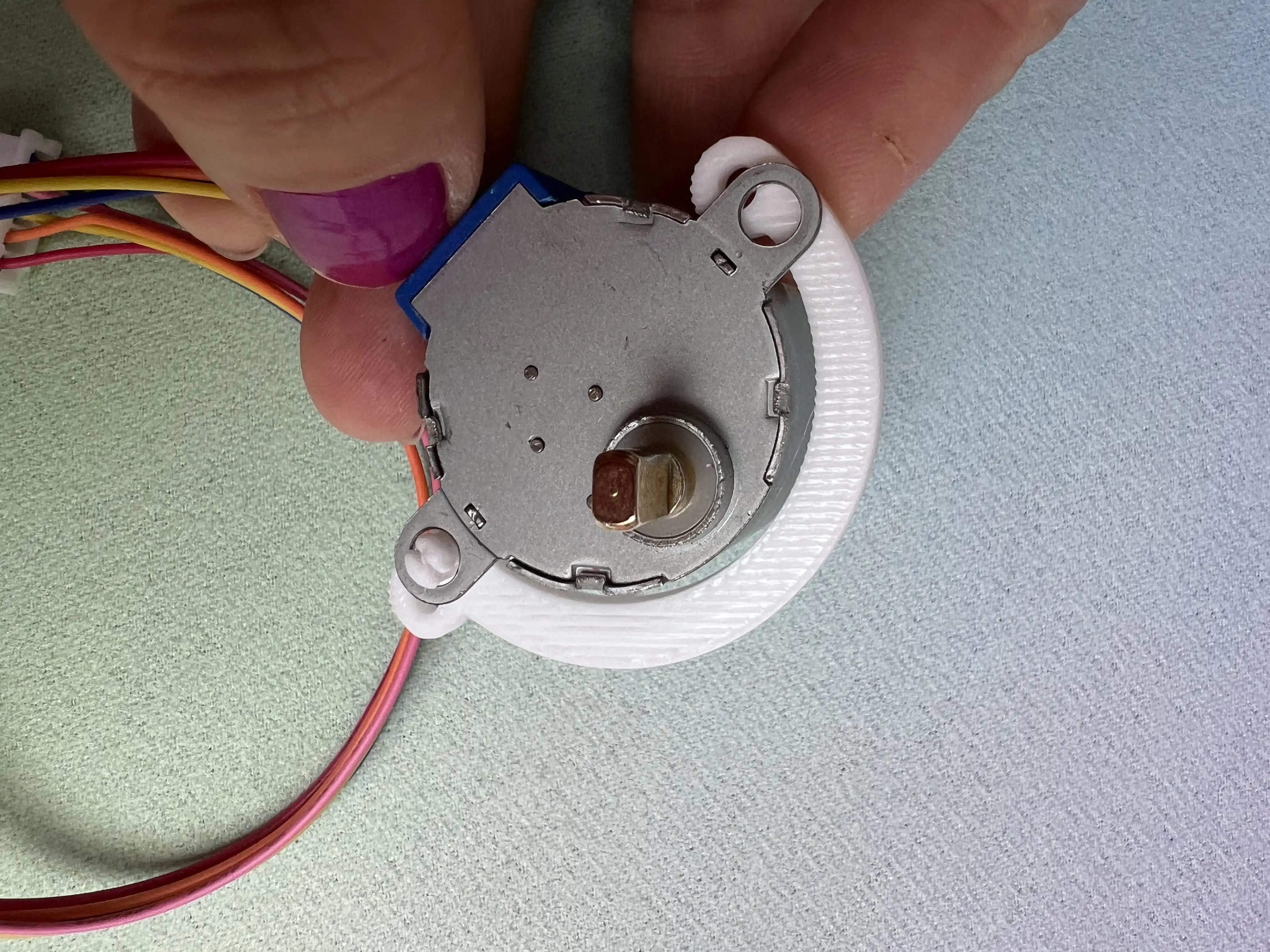
A motor that does not fit the grid
The Towards a Modular Grid study established a working connection rule for Artificial Emotion: mounting points should follow a 20 × 20 mm grid, with M3 fasteners as a practical starting point for small kinetic prototypes.
The 28BYJ-48 stepper motor, selected for the project's small-scale kinetic studies, introduces a mismatch. The specimen measured in the studio has 35 mm between the centres of its two original mounting holes. Those holes cannot both land on the chosen 20 mm lattice.
Rather than redesigning the grid around a particular motor, the experiment asks:
Can a small, removable adapter translate the motor's existing 35 mm mounting pattern into a 40 mm external connection span?
The adapter is a deliberately modest part. Its role is to make an off-the-shelf component participate in a common physical system without permanently modifying it.


Sketching the interface
The initial drawing proposes a U-shaped printed bracket running around the motor housing near the output-shaft side, away from the wire exit. One end uses an existing motor mounting hole and an M3 screw; the opposite end uses the motor's second hole for a press-fit retaining clip.
A new mounting ear extends beyond the clip to establish a 40 mm distance between the outer mounting centres. The additional 5 mm is placed on one side, rather than being divided symmetrically.
This asymmetry is intentional: it prioritizes a compact adapter that follows the existing motor geometry. It does not mean the motor shaft is centered on the grid.
From sketch to parametric model
The part was modeled in OpenSCAD, keeping the connection distances, screw clearance, bracket contour and clip geometry editable.
The mechanical idea combines three interfaces:
- Motor interface: two original mounting positions, 35 mm apart.
- Fastening interface: an M3 screw on one side and a snap-fit clip on the other.
- System interface: the outer attachment positions are 40 mm apart, or two 20 mm grid intervals.
The curved body follows the motor casing with some clearance so that the printed U can be installed without relying on deformation of the entire bracket.
The clip is a separate mechanical challenge. It needs enough compliance to pass through the existing motor hole and enough retention to resist being pulled back out. In PLA, increasing the interference too far may improve grip at the cost of making the clip brittle.
First print — V01
The first PLA print was installed on an actual 28BYJ-48 motor. The physical test confirmed that the overall U-shaped contour, hole positions and 40 mm outer span worked for this specimen.
The part could be positioned around the motor, and the mounting concept was viable without modifying the motor itself.
The weakness was the snap-fit retention: the clip entered the motor hole too loosely. It located the bracket but did not provide the positive click and hold intended in the sketch.
This was a useful result because the mismatch was local. There was no reason to redesign the grid dimensions or the main body of the adapter.
Revising the clip — V02
The second digital iteration keeps the successful V01 body and connection geometry, concentrating on the clip.
In the V02 model, the clip's total height is increased from 4.5 mm to 6.5 mm, and the retaining head's diameter from 4.4 mm to 4.7 mm. The intention is to create a more definite engagement through the motor's mounting hole.
These adjustments should not be confused with a validated improvement. V01 has been physically tested; V02 is a proposed revision awaiting its own print-and-fit test. The next test will need to establish whether the revised clip grips more securely without cracking or requiring excessive force.
Parametric fabrication
The editable OpenSCAD source is the working definition of the connector. The STL records a specific printable iteration.
Fabrication files:
- V02 — OpenSCAD: View / download source
- V02 — STL: View / download STL
The model is designed for FDM printing in PLA. Final printing orientation, clearances and clip tolerances should be documented after the V02 test rather than assumed from the digital geometry alone.
What worked
The V01 test establishes that a small printed interface can reconcile the motor's 35 mm mounting geometry with a 40 mm connection span compatible with the 20 mm grid. The bracket follows the actual motor casing while leaving the motor intact and removable.
The experiment also confirms the value of making small connectors parametric: an isolated retention problem can be iterated without disturbing the dimensional rule shared by the larger system.
What remains unresolved
The V02 clip still needs physical validation: insertion force, retention, repeatability over several assembly cycles, and possible PLA damage. The practical clearance of the new M3 mounting ear and the way this asymmetric adapter locates the shaft relative to other OS20 components also deserve attention during assembly.
What this study is testing
The point of adopting a common grid is not to force every commercial object to share the same dimensions. It is to develop interfaces that translate between different geometries.
The 28BYJ-48 brings its own mounting pattern; Artificial Emotion brings a shared construction rule. The adapter negotiates between them:
35 mm motor mounting pattern → removable printed interface → 40 mm OS20 connection span
A small bracket can therefore become a repeatable component in a larger family of kinetic studies, rather than an isolated fix for a single prototype.