Studyexperiment
OS20 Plate Generator
Turning the 20 mm mounting grid into a parametric laser-cut plate
A small fabrication tool for generating laser-cut plates from the Artificial Emotion 20 mm modular grid, with optional edge conditions for wooden frames and M6 structural connections.
Question
How can the 20 mm mounting grid developed for Artificial Emotion become a reusable fabrication system rather than a pattern that has to be redrawn for every new plate?
The OS20 grid had already become a useful rule for connecting kinetic prototypes: a fixed 20 × 20 mm lattice and M3 mounting points make it possible to design brackets, mechanisms and supports that can relate to the same underlying structure.
But once I began using different wooden frames and plate sizes, the grid also became a fabrication problem.
Every new plate had a different width and height.
I did not want to resize the grid to make it fit.
The 20 mm spacing needed to remain constant.
The question became how to generate the largest possible grid from the centre of any plate outward, while allowing whatever space remains to stay at the edges.


From grid to generator
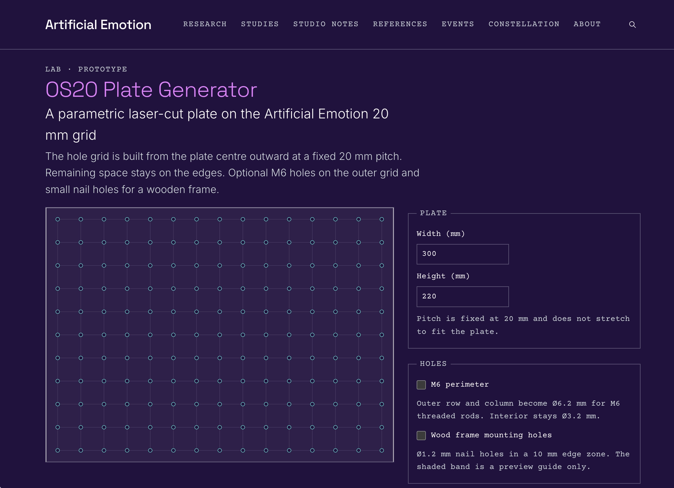
Instead of drawing each laser-cut plate manually, I built a small web-based Lab:
The generator takes the plate width and height in millimetres and constructs the OS20 lattice from the centre.
The pitch is always 20 mm.
If the plate dimensions are not multiples of 20, the grid is not stretched or redistributed. It simply grows symmetrically from the centre until another row or column would no longer fit.
The leftover dimension remains as margin around the grid.
This matters because the grid is not decorative.
It is a shared mechanical reference.
Changing its spacing to accommodate a particular plate would break the relationship between that plate and the other OS20 parts already being developed.
Hole system
The standard OS20 points are generated as Ø3.2 mm clearance holes for M3 fasteners.
The generator also introduces an optional structural perimeter.
When M6 perimeter is enabled, the outermost generated row and column change from Ø3.2 mm to Ø6.2 mm, while the interior remains M3.
This creates another possible scale of connection without changing the 20 mm lattice itself.
The M3 grid can hold small mechanisms and interfaces.
The larger perimeter holes can accept M6 threaded rods, making it possible to imagine two plates connected in parallel, open boxes, frames, spacers or larger structural assemblies.
The larger connection is therefore not a second grid.
It is another use of the same grid at its boundary.
The wooden frame edge
A second requirement came directly from the wooden frames I was already using in the studio.
The frames cover a narrow zone around the edge of the plate and are fixed with very small nails.
For this reason, the generator includes an optional Wood frame mounting holes mode.
The final 10 mm edge zone is treated separately from the OS20 field and can receive small Ø1.2 mm nail holes.
This edge condition is intentionally different from the modular grid.
When the frame zone is active, it should remain available for fixing the plate to wood rather than being occupied by normal OS20 holes.
This is a small detail, but it reflects the reason for making the generator in the first place: the plate has to negotiate between a repeatable modular system and the practical conditions of how it is mounted, exhibited and assembled.
A fabrication Lab
The Lab is deliberately small.
It currently deals only with the geometry needed to make the plate:
- plate width and height;
- fixed 20 mm grid;
- Ø3.2 mm M3 clearance holes;
- optional Ø6.2 mm M6 perimeter;
- optional Ø1.2 mm wooden-frame mounting holes;
- a live 2D preview;
- SVG export for laser cutting.
It does not try to become a general CAD application.
There are no material presets, laser settings, arbitrary grid pitches or fabrication recipes.
The exported SVG contains the plate outline and hole geometry at physical scale in millimetres.
The intention is that the same small tool can generate different plates while keeping the connection logic stable.
Observation — 20 October 2026
At this stage, the Lab establishes the geometry and produces fabrication files, but I have not yet laser-cut a generated plate to test the result physically.
That distinction is important.
The 20 mm grid itself comes from previous physical experiments, and the M3 relationship has already been used in other OS20 parts.
What is new here is the translation of that system into a parametric plate generator and the introduction of the two edge conditions: the wooden-frame fixing zone and the M6 structural perimeter.
The next test is therefore not whether the interface can draw the geometry.
It is whether the generated geometry behaves as expected when it becomes a real plate.
Next
The first physical test should check:
- whether the SVG imports at the correct 1:1 scale;
- whether Ø3.2 mm gives the intended clearance for M3 hardware after laser cutting;
- whether Ø6.2 mm works cleanly with M6 threaded rod;
- whether the 1.2 mm holes behave correctly with the small frame nails;
- whether the 10 mm frame zone corresponds to the real wooden frames;
- whether the centred grid produces useful margins across different plate dimensions.
A photograph of the existing wooden frames and a screenshot of the generator can document the two sides of this experiment: the physical need that produced the question, and the digital tool built in response to it.
The Lab is not separate from the fabrication research.
It is becoming one of the tools through which the physical system itself is designed.