Studyexperiment
Towards a Modular Grid
Developing a shared mounting language for kinetic prototypes
An ongoing study of a 20 mm modular grid, M3 connections and 3D-printed interfaces for mounting, combining and exhibiting the physical mechanisms of Artificial Emotion.
Why a common grid?
The need for a common mounting system emerged from a very practical question: how can the growing collection of Artificial Emotion mechanisms be suspended, rearranged, tested and exhibited without designing an entirely new attachment for every prototype?
The first experiments were being prepared for a mobile display structure in the studio. A horizontal tube could support small kinetic modules, but each mechanism still needed a way to connect its own body to the shared structure.
The initial response was to design a custom 3D-printed clamp for the tube. That immediately raised a broader question: if the clamp is custom-made, what should determine the positions of its mounting holes?
Rather than designing each part in isolation, the research began to consider a shared geometric rule.
A common grid turns individual attachments into parts of a larger system.
The aim is not to make every mechanism identical. It is to make their points of connection intelligible to one another.
OpenStructures as a reference
An important reference is OpenStructures, an open modular design system initiated by Thomas Lommée. Its components are developed around shared geometric principles so that parts designed independently can be combined, adapted and reused.
The OpenStructures grid is organized around 40 × 40 mm squares. Its design principles also position relevant connection or perforation centres at multiples of 20 mm.
These are two related measurements, but they are not the same thing:
- 40 mm describes the principal square geometry of the reference grid;
- 20 mm is the interval used for many connection-centre coordinates;
- hole diameter is a separate specification and depends on the hardware and part.
OpenStructures does not require every component to use one universal hole diameter. Its documentation discusses different fastening families, including M2.5, M5 and M10.
For Artificial Emotion, the intention is to borrow the 20 mm connection logic, rather than to claim that every new component automatically becomes compatible with every OpenStructures part.
The working rule is simple:
Connection points are located on a 20 × 20 mm grid. The fastener system is specified separately.
This is a design decision as much as a technical convenience. It leaves the geometry open to later mechanisms and future collaborators.
Comparing existing grids
The study began by comparing the dimensions of readily available perforated hardboard with the geometry of the mechanisms themselves.
A white perforated hardboard panel sold by JUMBO in Switzerland was measured directly with a caliper:
| System or component | Centre-to-centre spacing | Hole diameter |
|---|---|---|
| JUMBO perforated hardboard | 25 × 25 mm | Ø4 mm, measured |
| Brazilian Eucatex pegboard, observed reference | 12.5 × 12.5 mm | Not established |
| OpenStructures connection geometry | Multiples of 20 mm | Depends on the part |
| Artificial Emotion proposed interface | 20 × 20 mm | Ø3.4 mm clearance for M3 in printed parts |
| 28BYJ-48 stepper motor, studio specimen | 35 mm between mounting centres | To be checked per motor variant |
The 25 mm pattern is not unique to the Swiss panel. Similar perforated hardboard products are available in France, often marketed as panneau perforé en Isorel and sold with ready-made hooks and tool-storage accessories. This is useful for the display system, which may need to be reproduced outside Switzerland.
But commercial availability is not, by itself, a sufficient reason to make a particular pegboard the underlying standard for every mechanism.
A 25 mm commercial grid and a 20 mm construction grid do not coincide at every point. With aligned origins, their connection coordinates meet again at 100 mm intervals. A small intermediary plate, mounting rail or other interface will therefore be required to attach some OS20 components to the commercial pegboard.
For the moment, that is an acceptable separation:
The pegboard is a display surface. The 20 mm grid is the internal language of the prototypes.
The motor does not determine the grid
The 28BYJ-48 stepper motor is the selected motor for the small kinetic studies of Artificial Emotion. It is compact, accessible and sufficient for exploring motion before larger installations require other actuators.
The motor used in the studio has 35 mm between the centres of its two mounting holes, measured directly with a caliper.
That dimension does not fall on a 20 mm grid. It would not fall directly on the 25 mm commercial pegboard either.
The initial temptation was to look for a grid that matched the motor. But the motor is only one component in a much larger family of mechanisms, sensors, spools, supports and housings. Other commercial parts will bring other dimensions.
The decision is therefore to keep the 20 mm modular grid and develop a motor bracket whose external mounting points follow that system while its internal geometry accommodates the 35 mm motor pattern.
This distinction is fundamental:
- the component interface respects the manufacturer's actual geometry;
- the system interface respects the shared construction grid.
The adapter is not an accidental exception. It is one of the basic tools that allows a modular system to work with real-world parts.
Defining the Artificial Emotion interface
The first working specification is deliberately modest.
| Property | Working specification |
|---|---|
| Connection grid | 20 × 20 mm, centre to centre |
| Preferred hardware | M3 metric fasteners |
| Nominal clearance hole in 3D-printed parts | Ø3.4 mm |
| Fabrication methods | FDM printing, laser-cut sheet material, drilled or milled parts |
| Coordinate principle | Connection-centre positions in 20 mm increments from a defined origin |
| Status | Working standard, subject to physical validation |
Grid spacing and hole diameter are independent variables. The 20 mm grid describes the distances between connection coordinates. The Ø3.4 mm hole describes one practical implementation for an M3 clearance fit in a 3D-printed part; it is not a universal hole diameter for all materials or every OpenStructures component.
A part also needs to define its origin and orientation. Without those two pieces of information, two sets of holes can each have 20 mm spacing but still fail to align when assembled.
In future drawings, these parameters should be documented together with part thickness, material, edge clearance and fastening method. For laser-cut 3 mm MDF or other thin sheet materials, the exact hole clearance and minimum material around each hole must be tested rather than copied uncritically from a printed PLA part.
The goal is to establish a small number of reliable interfaces, not to perforate every surface simply because a grid exists.
The first component: a clamp for MITTZON
The first part redesigned around the grid is a saddle-shaped clamp for the Ø25 mm hanging tube of an IKEA MITTZON mobile frame.
The frame is part of the studio's developing living archive of prototypes: a movable structure that allows mechanisms to remain visible, accessible and suspended while they are being developed.
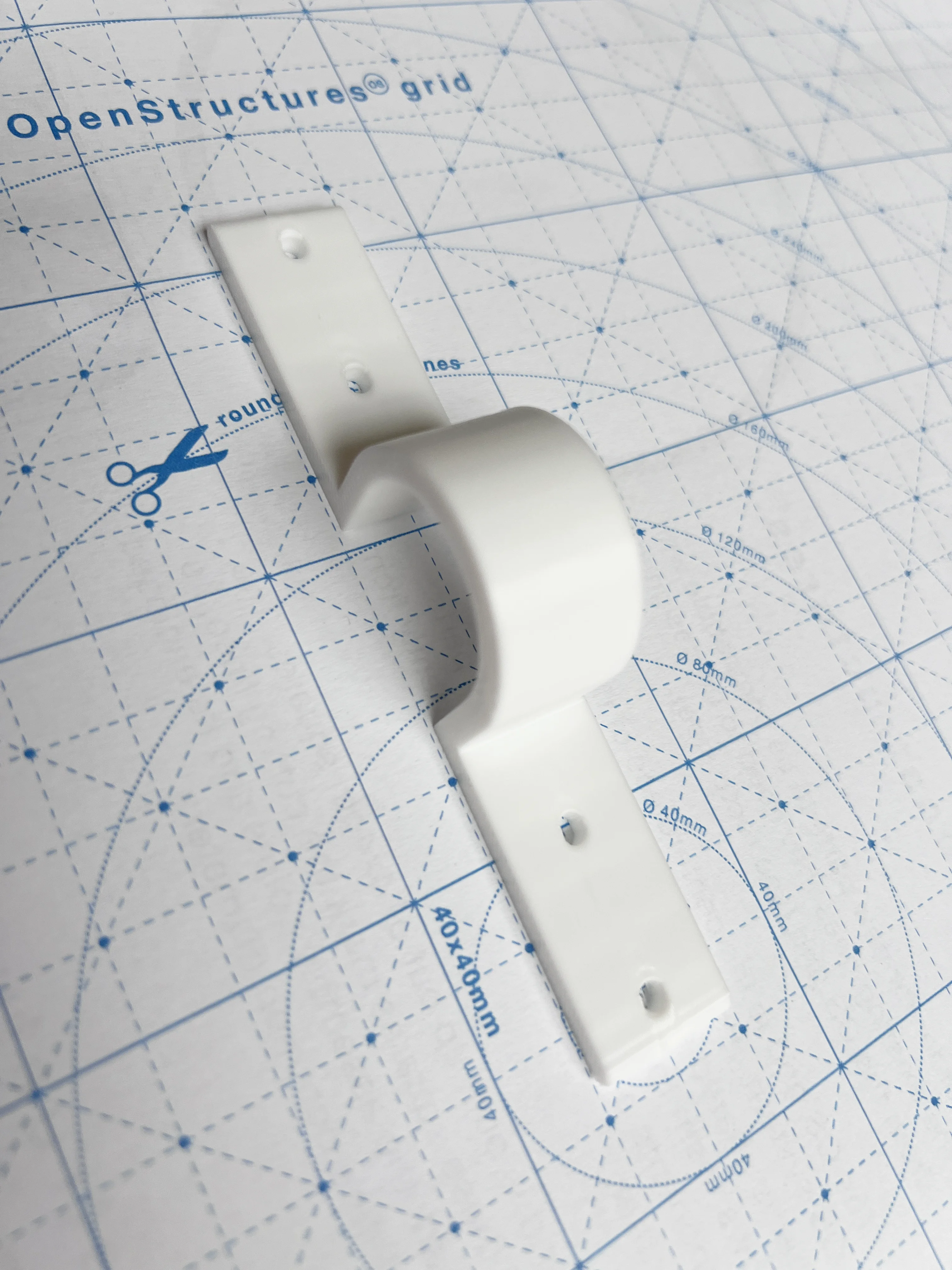
The clamp has a curved U-shaped centre that passes over the tube and flat wings that can be screwed to the top of a prototype housing.
The earliest design was based on an ordinary pipe saddle: a curved bracket with holes in its two flat ends. A printed version introduced wider mounting wings and rounded corners. At that stage, the holes had been positioned primarily for the individual clamp, not for an explicitly defined family of future components.
Redesigning it around OS20 changed the problem. The clamp was no longer just a way to hold one object on a tube. It became the first candidate for a repeatable system connector.
Clamp geometry: OS20 version 0.3
The OS20 version introduced four nominal M3 clearance holes, with two positions on each wing.
The model uses the following design parameters:
| Parameter | v0.3 |
|---|---|
| Tube nominal diameter | 25 mm |
| Internal saddle diameter | 25.6 mm |
| Wall thickness around the arch | 4 mm |
| Wing/base thickness | 4 mm |
| Width along the tube | 18 mm |
| Overall wing-to-wing length | 112 mm |
| M3 clearance holes | Four, Ø3.4 mm |
| Hole positions along the length | −50, −30, +30, +50 mm from saddle centre |
| External wing corner radius | 1.8 mm |
The holes are 20 mm apart within each wing, and 60 mm apart across the central opening. Their successive intervals are 20, 60 and 20 mm — all multiples of the chosen grid unit.
One geometric detail matters: the tube centre sits halfway between grid columns if those four mounting holes define the grid origin. In other words, the connection holes belong to a regular OS20 lattice, but the saddle is offset by 10 mm relative to that lattice.
This does not invalidate the mounting pattern. It does mean that a consistent datum must be specified whenever the connector is included in a larger assembly.
The first OS20 shape was exported from OpenSCAD as a printable STL.
Testing the actual structure
A physical mounting test with an early MauMau cardboard housing exposed a problem that was difficult to judge from the digital model alone.
The clamp could hang the box from the tube, but the box did not sit firmly enough against the attachment. There was too much vertical clearance between the tube and the flat mounting plane.
The issue was not the grid or the number of holes.
It was the depth of the U-shaped section.
This changed the next design decision. Rather than adding material below the housing to compensate for the gap, the bracket itself would be shortened. A slightly short bracket could later be shimmed with a spacer if necessary; an unnecessarily deep bracket would leave the prototype unstable.
This small test illustrates why the modular system must develop through physical assembly, not only through diagrams.
Clamp geometry: OS20 version 0.4
Version 0.4 preserves the tube diameter, the four mounting holes, the rounded external corners and the general clamp shape.
The main change is a 6 mm reduction in the straight-leg height reference, bringing the saddle closer to the module's top plane.
In the parametric OpenSCAD model, the arch centre parameter changes from 17 mm to 11 mm relative to the underside reference. The overall profile height is correspondingly reduced from approximately 33.8 mm to 27.8 mm.
The 4 mm thickness of the flat wings remains part of the geometry; it is not subtracted twice.
This is a proposed correction based on the physical test, not yet a validated final connector. The printed v0.4 still needs to be tested on the MITTZON tube with the MauMau housing, checking fit, stability, fastener access and PLA deformation under load.
The grid makes the mounting pattern repeatable. The physical test makes the connector usable.
Parametric fabrication
The clamp is written in OpenSCAD so the critical dimensions can remain editable rather than disappearing into a single fixed mesh.
The current model exposes parameters for the tube diameter, tolerance, wall thickness, strap width, wing reach, M3 clearance holes and the height of the saddle.
Two working model versions are documented:
- OS20 v0.3: first four-hole grid-based clamp;
- OS20 v0.4: same interface, with the U shortened by 6 mm.
Model files:
The STL is useful for printing or sharing a particular iteration. The OpenSCAD file is more useful for adapting the connector as the system evolves.
What worked
The process has established several useful principles:
- a commercial furniture system can become a stable reference for a family of custom connectors;
- the positions of mounting holes can be governed by a common 20 mm rule rather than improvised part by part;
- M3 fasteners are proportionate to the small-scale studies being developed;
- a parametric model makes changes to the saddle geometry straightforward;
- testing with an actual cardboard housing reveals mechanical constraints that are not obvious on screen;
- the display structure and the mechanisms can be developed as separate, connected systems.
The most significant result is not yet a finished clamp. It is the decision to treat each new mechanism as a possible contributor to a shared family of parts.
What remains unresolved
Several questions are still open:
- Which mounting-hole configurations work best for small MDF housings without weakening their surfaces?
- How will the 35 mm mounting pattern of the 28BYJ-48 connect to an OS20 exterior?
- How can components on a 20 mm grid attach neatly and reversibly to a commercially available 25 mm pegboard?
- Which tolerances should change when the same geometry is printed in PLA or cut in sheet material?
- How should orientation, fastener access and load limits be documented for other people reproducing the system?
There is no need to solve all of these questions before using the grid. They are the work that will test whether the proposed rule is productive.
Next iteration
The next physical steps are to print and test the shorter clamp, then redesign the MauMau housing so its external connection holes sit on the 20 mm grid.
After that, the same rule can be applied to a compact 28BYJ-48 motor bracket, small support plates, pulley mounts and other kinetic components.
In parallel, a separate interface can be developed for the JUMBO pegboard. That adapter should connect the chosen internal grid to the commercially available display surface without changing the rules inside each prototype.
A further documentation step will be to host the STL and source models on the Artificial Emotion website, possibly with an embedded interactive model viewer.
What this study is testing
The study began with a mounting clamp, but the underlying question is about how a physical research practice can become more cumulative.
Each iteration currently teaches something about a specific material, mechanism or connection. Without shared dimensions, those discoveries risk remaining isolated in individual objects.
A modular grid is a way of carrying knowledge from one prototype to the next.
It is also a way of keeping the research open to adaptation: a motor can change, a housing can be remade, or a new display can be built in another city without having to reinvent every attachment.
individual mechanisms → shared interfaces → a reusable physical research language
For Artificial Emotion, the grid is not an aesthetic constraint or a claim that every object should look modular.
It is an underlying rule that allows different kinetic behaviors to coexist, be compared and continue evolving.