Objeto Cinético C-15 — Abraham Palatnik
Abraham Palatnik · 1969–2001 · artwork
A kinetic object in which guided metal elements, motors, magnets, layered movement and shadows turn mechanical precision into a delicate spatial choreography.

Photo: Abraham Palatnik, Objeto Cinético C-15, 1969/2001. Source: Nara Roesler.
Objeto Cinético C-15 — Abraham Palatnik
Metadata
- Artist: Abraham Palatnik (1928–2020)
- Title: Objeto Cinético C-15 / Kinetic Object C-15
- Date: 1969/2001 (most gallery documentation); 1969/2011 in one exhibition catalogue — unresolved discrepancy
- Series: Objetos Cinéticos / Kinetic Objects
- Materials (catalogued): motor, industrial paint, Formica, wood, metal, magnets
- Dimensions: 77 × 90.5 × 15 cm (some listings give 14.9 cm depth)
- Collection: listed as a private collection in A Reinvenção da Pintura; present owner and permanent location not independently verified
- Research status: selected work for mechanical study and reproduction, with the original operation still to be documented
Why this particular work?
I have already chosen C-15 as the Palatnik work I want to study and reproduce. What caught my attention is not only its kinetic vocabulary, but its peculiar sense of order without rigidity.
There are thin lines, curved trajectories, discs, small colored objects, motors, joints, and what appear to be extraordinarily ordinary metal connectors. Everything looks almost provisional, and yet the overall choreography feels carefully composed.
It reminds me of a ballerina: precise, delicate, technically disciplined, but never visually heavy. This is a personal response to the image, not a claim about Palatnik’s intentions.
And there is something else I want to understand: this is not simply a moving composition on a flat surface. It is a physical drawing distributed across depth.
The photograph already suggests several spatial layers, overlaps and shadows. I want to understand how much of the perceived movement comes from the motors themselves, and how much comes from the relationship between moving components, fixed guides, the viewing angle and the wall behind them.
In other words, I am interested in the machine and in the visual conditions that allow the machine to become a composition.
The work’s historical moment: 1969
By 1969, Palatnik had already spent approximately two decades investigating the relationship between machines and visual perception.
His first Aparelhos Cinecromáticos (Kinechromatic Devices), begun around 1949, concealed moving mechanisms behind a luminous surface. Motors and colored lights produced an image that changed over time, while the machinery itself remained largely out of sight.
Abraham Palatnik. Aparelho cinecromático S-14 (Kinechromatic Apparatus S-14. 1957–58). source
In 1959, works such as Mobilidade IV explored movement through magnetic effects. By 1964 he began the Objetos Cinéticos, where moving rods, structures, motors and mechanical relationships became visibly part of the work.
The Relevos Progressivos, emerging in the mid-1960s, extended his investigation of sequence and optical movement to materially structured surfaces that did not necessarily require a motor.
So C-15 is not Palatnik’s first experiment with kinetics. It belongs to a mature phase, after he had already investigated light as movement, invisible forces, and movement as a visible material.
Photo: Objeto Cinético, 1964. source
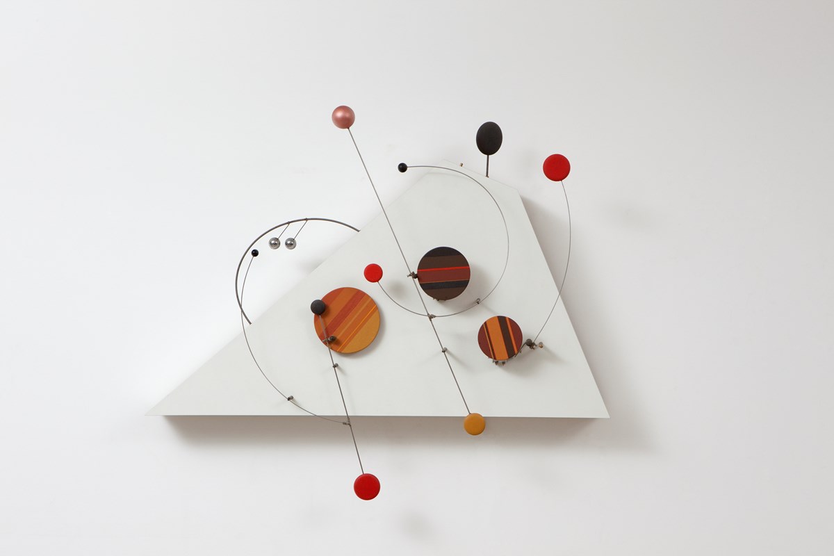 Photo: Objeto Cinético K-06, 1966.
He was also an industrial inventor
This is especially significant to me, because his industrial work was not some unrelated early apprenticeship that he later abandoned. It was happening alongside his artistic research.
In 1952, Palatnik developed a machine to break open the hard shell of the babassu palm nut without damaging the kernel, following months of research. This was a practical manufacturing problem with direct economic consequences in northeastern Brazil.
In 1968, only a year before the original date of C-15, he designed devices to improve the feeding of machinery used in fishmeal production. He also worked on a more economical, less polluting way to repackage a specialized powder used in dental materials.
These inventions are documented by Frederico Morais and in the Nara Roesler / A Reinvenção da Pintura materials.
I think this matters enormously. He did not merely use a motor because motors looked modern. He had hands-on experience solving problems involving transmission, feeding, handling, mechanical regularity, production and constraints.
Does this prove that a particular industrial invention directly informed C-15? No. But it changes the way I look at the piece. I see a working knowledge of mechanisms, not just an aesthetic fascination with machines.
A moving drawing occupying several planes
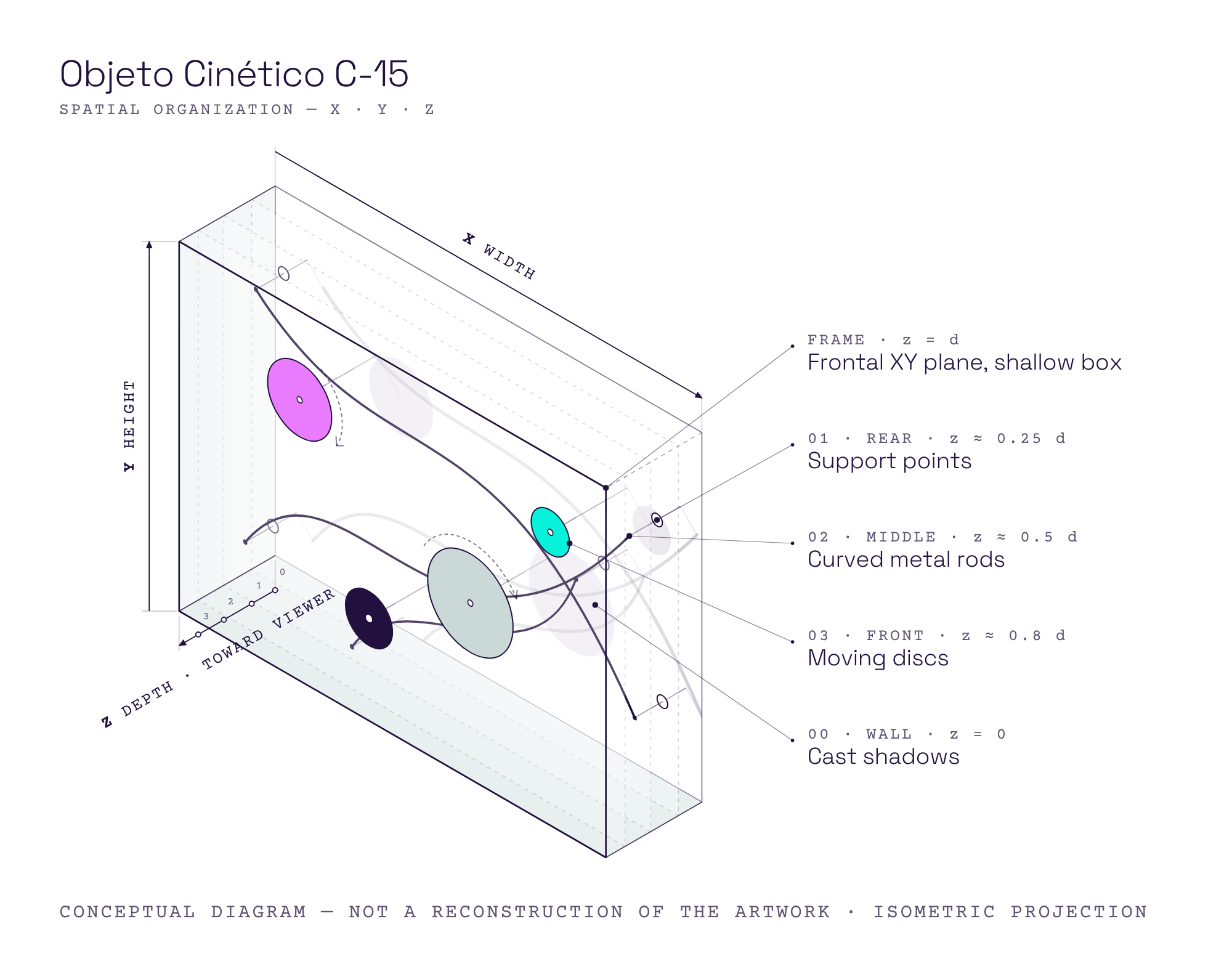
I initially described the piece as working between the wall plane and a second plane that projects into the room. For consistency in technical documentation, I will use this convention:
- X: horizontal, left to right;
- Y: vertical, bottom to top;
- Z: depth, perpendicular to the wall;
- XY plane: the frontal composition, parallel to the wall;
- Z axis: the separation between physical layers.
The distinction is important because the frontal photograph can collapse depth into a single drawing. But the object’s roughly 15 cm depth allows different components to occupy different positions along Z.
As a consequence, two rods can cross visually without necessarily intersecting mechanically. A moving disc can pass in front of or behind another element. The background receives shadows that add another layer of lines and forms.
The effect is not just sculpture plus motion. It is closer to a three-dimensional graphic composition whose image keeps being recomposed in time.
And one warning for the reconstruction: not every line in a frontal photograph is necessarily metal. Some visible curves and marks may be cast shadows. A photograph with a different light direction, and ideally a side view, is necessary to distinguish the actual construction.
Why the shadows matter
The cast shadows make the machine’s geometry appear to multiply. A rod and its shadow are similar lines with different spatial positions. As the rod moves, the shadow also moves, but its displacement depends on the light source and the distance to the background.
This means that the work may have at least three simultaneously active graphic systems:
- the physical moving elements;
- their apparent crossings and overlaps when viewed from the front;
- the projected shadows.
For a study model, lighting should be treated as a variable to investigate, not simply as exhibition infrastructure.
Looking closely at the mechanics
Here I need to separate what the photograph shows from what I think the mechanism might be doing.
1. Curved moving rods
Some thin metal elements have deliberately curved shapes. They could be fixed to rotating axes, attached to linkages, or used as moving supports for discs and small masses. The curvature can make a simple rotation look more like a gesture or a sweep.
A curved rod does not necessarily imply that the rod itself is a mechanical guide. In many cases it may simply be the visible moving element.
I want to measure what the tips of these rods actually do over time: full rotation, limited oscillation, an eccentric path, or a more complicated path transmitted by another linkage?
 Photo: Kinetic Object, 1999 source
2. Fixed mechanical guides and pins
This is a separate category from the expressive curved rods.
I can see what appear to be guide elements mounted at fixed points in the composition, including small pins or supports. These are the components I have been calling dutos: not the decorative-looking curved lines above, but the physical guides through or against which a moving element can be directed.
A guide can constrain the position of an otherwise flexible or freely moving element, set an allowed route, prevent lateral displacement, or transform the path of an actuated part. Which of those functions is present here still needs to be established.
I want the reconstruction notes to distinguish:
moving rod ≠ fixed mechanical guide ≠ pivot ≠ support pin.
They may look similar in a photograph, but they serve different mechanical roles.
 Photo: Objecto Cinético, 1968/2006. source
 Photo: source
3. Very ordinary connectors
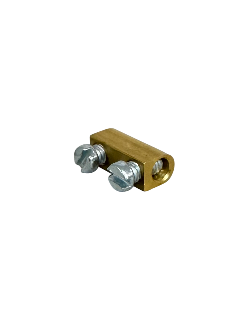
One detail I find particularly exciting is what looks like a small two-screw terminal connector, of the kind used to connect wires or clamp metal pieces together. I use similar commercial connectors in my own prototypes.
I cannot identify the part conclusively at this image resolution. But it raises a beautiful material question: how much of this finely balanced composition depends on purpose-made machinery, and how much on standard, inexpensive, readily available parts?
Before attempting to solder everything, I want to investigate whether adjustable screw-clamped connections were part of his actual construction vocabulary. They would allow rods to be positioned, tested, adjusted and replaced.
This would connect Palatnik’s precision to something very close to tinkering: iterative construction with accessible mechanical components. That is a reading I want to test, not an established account of how he built this exact object.
4. Motors along the lower edge
The frontal image shows several mechanical-looking assemblies near the bottom of the frame, and another assembly toward the left-middle area. They suggest distributed actuation rather than a single motor hidden behind the entire composition.
However, a frontal photo does not tell us which components are actual motors, which are gearboxes, and which might be passive couplings or bearings. Neither the number of motors nor their type, voltage, gearing, speed or control method has been confirmed for C-15.
I want a rear view, a detail of the drive shafts, and ideally footage of a full operating cycle before deciding how to reproduce the original movement distribution.
 Photo: Chromatic gears move the artwork. source
5. Magnets — an intriguing hypothesis about control
The gallery’s technical description explicitly includes magnets and a motor. But it does not explain their function.
My first hypothesis is that Palatnik may have used DC motors and magnets as part of a position-detection, switching or mechanical-control arrangement — a possible form of magnetic indexing or encoding. It is a direction worth investigating, especially if there were magnetic switches or other detectors involved.
But the evidence is not sufficient to call this a confirmed encoder. A magnet alone does not encode position; some additional sensing or switching arrangement would be needed. The magnets could also participate in attraction, repulsion, coupling, or another movement-related function.
Before assigning them a role, I need to establish:
- where each magnet is mounted;
- whether it moves or remains fixed;
- whether there are visible contacts, reed switches or sensors;
- whether the motion repeats at fixed angular intervals;
- whether the motor reverses, stops or continues at steady speed.
So I will keep magnetic position control / indexing as a working hypothesis, not a description of the original mechanism.
Why this looks choreographed rather than chaotic
One of my strongest impressions is that there is a lot of freedom in the drawing, but not a lot of randomness in how it is organized.
This is where comparison with other kinetic artists is useful, without turning this reference into a comparative catalogue.
In Calder, a mobile’s behavior can be highly sensitive to gravity, balance and ambient air. In Tinguely, motors and transmissions often bring friction, irregularity, apparent disorder and mechanical absurdity into the work.
Palatnik’s C-15 seems to offer a different possibility: a controlled system that produces a surprisingly gentle, almost bodily visual rhythm.
This is only a provisional reading until I see the machine operating. The photograph makes the composition look precise, but it does not prove that its timing is regular, that the parts are synchronized, or that there is no chance in its behavior.
Still, the question is compelling:
How can a relatively simple mechanical system produce something that feels like a choreography rather than a mechanical demonstration?
For me, that question is at the heart of this study.
Documentary history and the double date
The artist and gallery documentation usually dates C-15 1969/2001, and records its materials and dimensions consistently. The catalogue Abraham Palatnik: A Reinvenção da Pintura, however, lists 1969/2011 for the same title and dimensions.
I do not yet know whether this is a catalogue error, a different reconstruction date, or a distinct documentary convention.
Nor can I claim that 2001 was definitely the date of fabrication, restoration or re-creation. The two-part date indicates that the work’s history requires explanation, but the specific relationship between the two years must be verified.
Documented appearances include:
- 2005: Cinético Digital, Itaú Cultural, São Paulo;
- 2012: Abraham Palatnik, Galeria Nara Roesler, São Paulo;
- 2013–2015: A Reinvenção da Pintura, various Brazilian venues;
- 2026: O fascínio e o afeto, Galeria Nara Roesler, São Paulo.
The catalogue of A Reinvenção da Pintura identifies a private collection. The current owner and permanent location remain unconfirmed.
What I want to reproduce for Artificial Emotion
This work is already selected for study and reproduction. The open question is not whether to study it, but which mechanical behavior to isolate first, and how faithfully the original configuration can be reconstructed from available evidence.
The first study does not need to duplicate every line, disc, connection and motor. It should investigate the underlying relations:
- fixed guides versus moving rods;
- one or more mechanically driven paths;
- components occupying different depths;
- apparent crossings when seen from the frontal XY plane;
- cast shadows as a second drawing;
- simple components producing a disciplined yet delicate motion.
For a first exploratory module, I can use my established 28BYJ-48 study motor for Artificial Emotion, small metal rods, an adjustable mechanical connection, and a rigid support that allows more than one Z position. This is a contemporary study choice, not evidence that Palatnik used that motor or that configuration.
I would not begin by specifying an elaborate electronic control system. I want to understand the geometry first: where the guides are fixed, how the moving elements are constrained, and what trajectories their ends trace.
Only after that should I decide whether the next version calls for one motor, several independent motors, gears, an eccentric linkage, magnetic sensing or some other approach.
Study questions
- How does a fixed eyelet or pinned guide change the motion of a slender rod or filament?
- Can a small set of regular mechanical motions create a complex image through layering?
- What happens when the same composition is viewed head-on versus from the side?
- How much does the apparent movement change with shadow distance and light direction?
- Which connections must be rigid, which adjustable, and which must act as bearings or pivots?
What I still need to research
- What explains the 1969/2001 versus 1969/2011 dating?
- How many motors are installed? What models, gearing and speeds?
- Which curved lines are moving rods, which are fixed guides, and which are shadows?
- Are the guide elements tubular, eyelets, wire loops or another form of constrained support?
- Which axes are fixed, and which joints rotate or slide?
- Are the moving parts synchronous, phase-shifted, independently driven or periodically reversing?
- Is there an original technical drawing, artist annotation, maintenance record, or conservation report?
A useful archive to consult next is the OLATS Palatnik material, including images of technical devices, although those should not be mistaken for verified schematics of C-15.
Why this matters for Artificial Emotion
What I want to take from Palatnik is not an aesthetic recipe involving circles and colored discs.
It is the possibility that mechanical precision can generate apparent delicacy.
In Ora X, Munari takes the regular motion of a clock and turns it into changing color relationships. In C-15, Palatnik seems to work through a richer spatial field: actual moving elements, guided paths, crossings at different depths, and the shadows that join them.
That shift matters to me. It suggests that a moving sculpture does not need complex software or a large vocabulary of gestures to become expressive. It can start with ordinary components, a few physical constraints, and carefully designed relationships in space and time.
I keep returning to the image of a ballerina: a physical system governed by strict rules that nevertheless appears light, fluid, and alive.
The question I want this study to answer is:
Can I construct a mechanism whose carefully constrained movement is perceived as a gesture — something that behaves — rather than merely a motor rotating an object?
Sources
- Galeria Nara Roesler — O fascínio e o afeto (2026), C-15 listing: https://nararoesler.art/en/exhibitions/306/works/
- Galeria Nara Roesler — Frieze New York care pack, Objeto Cinético C-15, 1969/2001, dimensions, materials and exhibition history: https://nararoesler.art/usr/documents/exhibitions/list_of_works_url_2/80/gnr-palatnik-frieze-ny-carepack-english.pdf
- Nara Roesler — Abraham Palatnik portfolio, including industrial inventions and the kinetic-object series: https://nararoesler.art/usr/library/documents/portfolios/gnr-abraham-palatnik-portfolio.pdf
- Nara Roesler — Abraham Palatnik exhibition (2012), section on babassu and fishmeal inventions: https://nararoesler.art/exhibitions/28/
- Fundação Iberê Camargo — Abraham Palatnik: A Reinvenção da Pintura (exhibition catalogue; C-15 catalogued 1969/2011): https://iberecamargo.org.br/wp-content/uploads/2018/10/catalogo_abraham-palatnik-a-reinvenccca7acc83o-da-pintura.pdf
- Sicardi | Ayers | Bacino — Progression (2017), C-15 reproduction and material listing: https://www.sicardi.com/exhibitions/abraham-palatnik/selected-works?view=slider
- OLATS — Abraham Palatnik archive and technical imagery (not necessarily C-15): https://www.archive.olats.org/pionniers/pp/palatnik/galerie.php