Studyprototype
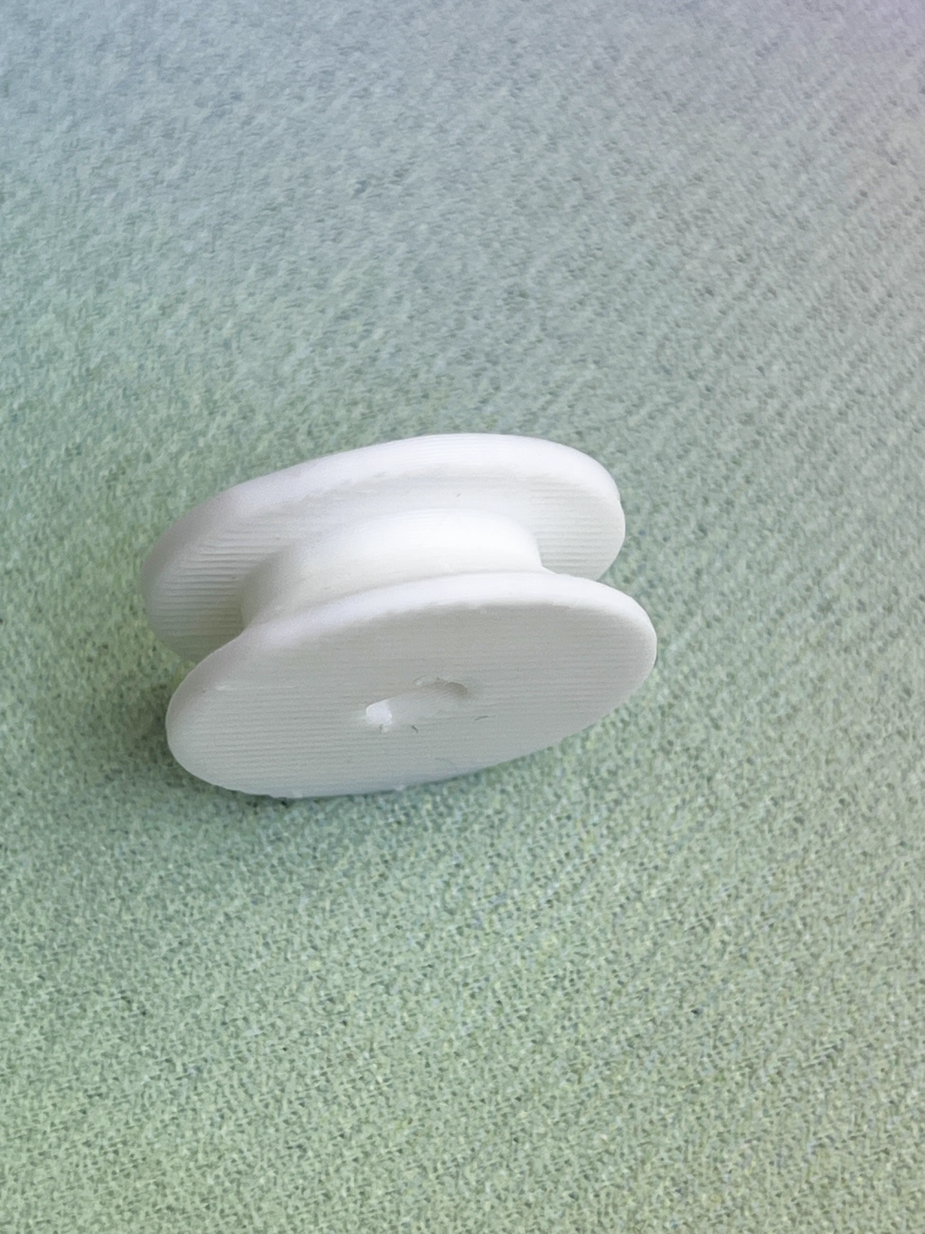
MauMau Spool — First Parametric Prototype
A parametric spool for the first MauMau kinetic module
A first parametric spool for the MauMau kinetic module, designed to couple a 28BYJ-48 stepper motor to braided fishing line and refined for FDM printing and line fixation.
Question
How can a very small 3D-printed spool connect directly to the 28BYJ-48 stepper motor and reliably manage a thin braided fishing line inside the first MauMau kinetic module?
At this stage, MauMau was being developed as a single-movement kinetic module: one motor, one line, one controlled movement.
The spool therefore had a very specific job.
It needed to couple directly to the motor shaft, wind and release the line, remain compact enough to fit inside the module, and be simple enough to fabricate repeatedly while the rest of the mechanism was still changing.


Setup
The line used in this first version was approximately 0.24 mm braided fishing line.
The spool was designed around the 28BYJ-48 geared stepper motor, attaching directly to its output shaft through the motor's double-flat shaft profile.
Rather than modelling the part manually as a fixed object, I asked Raven to build it parametrically in Grasshopper, so that the important dimensions could remain adjustable while the mechanism evolved.
The main dimensions of this first spool were:
| Parameter | Value |
|---|---|
| Core diameter | 15 mm |
| Core width | 5 mm |
| Flange diameter | 24 mm |
| Flange thickness | 1.8 mm |
| Overall height | approximately 8.6 mm |
| Fishing line | approximately 0.24 mm braided line |
The Grasshopper definition also included parameters for the shaft fit and insertion depth.
First geometry
The first idea was extremely direct:
flange → cylindrical core → flange
In other words, one flat tab on one side, the central winding surface, and another flat tab on the opposite side.
As a diagram, it made perfect sense.
As a 3D print, it did not.
One of the useful things about this study was seeing immediately that a mechanically understandable form is not automatically a printable form.
The upper flange would begin too abruptly above the narrower core, creating an unsupported horizontal transition.
For FDM printing, that geometry needed to grow upward progressively rather than appearing as a flat overhang.
Designing for the print
The next iteration introduced a 45° transition between the core and the upper flange.
That small change transformed the spool from a diagram of a spool into a part that could actually be fabricated cleanly.
The final orientation placed one flange flat on the print bed and allowed the opposite flange to grow through the tapered transition.
The spool remained visually and mechanically simple, but its geometry now contained information about the fabrication process itself.
This became an important principle in the MauMau development:
the fabrication method is part of the geometry.
The part cannot be designed independently from the way it will be made.
Working with Raven and Grasshopper
This spool was one of the early moments in which I started using Raven as part of the parametric fabrication workflow.
The process was short.
In roughly three prompt cycles, the part moved from a basic spool definition to a printable geometry that could be exported and tested physically.
The important part was not that Raven produced a finished object automatically.
The useful part was that the design remained visible as a Grasshopper definition.
I could inspect the dimensions, change the relationships between the core and flanges, adjust the motor interface and regenerate the geometry without rebuilding the part from scratch.
That made the spool useful not only as a component, but as an early test of a broader design method for Artificial Emotion:
describe relationships first, then fabricate a current state of those relationships.
Observation
The printed spool established a workable actuation chain:
28BYJ-48 → spool → braided fishing line → suspended element
At this scale, the dimensions were sufficient for the first MauMau tests.
The 15 mm core kept the part compact, while the 24 mm flanges gave enough lateral containment for the thin line.
The double-flat motor interface allowed the spool to attach directly to the stepper shaft without requiring a separate coupler.
The first printed version also made another missing detail obvious:
there was still no deliberate way to anchor the fishing line to the spool.
The line could be wrapped around the core, but the beginning of the line had no dedicated mechanical fixing point.
That remained unresolved in this first version.
What this prototype established
The first MauMau spool established the basic relationship between motor, line and fabrication.
It confirmed that:
- the spool could mount directly to the 28BYJ-48 shaft;
- a compact 15 mm core was sufficient for early movement tests;
- the line could be managed inside a 24 mm flange envelope;
- the spool should remain parametric while the module architecture evolved;
- the geometry needed to account for FDM printability;
- a 45° transition solved the unsupported upper-flange problem;
- line fixation needed to become an explicit feature rather than an improvised afterthought.
The spool was small, but it contained several of the questions that would continue through the MauMau module: motor coupling, line management, fabrication constraints, tolerances and the relationship between a digital definition and a physical mechanism.
---
Download / view spool STL
Download / view spool Grasshopper File
Update — 2 October 2026
After using the first printed spool, I returned to the Grasshopper definition to solve the missing line fixation.
The new version added a pair of localized anchor holes near the outer part of the spool.
The initial printed holes were too small to use comfortably with the line, so the hole diameter was increased to:
2.0 mm
The updated anchor parameters were approximately:
| Parameter | Value |
|---|---|
| Anchor hole diameter | 2.0 mm |
| Anchor radius | 9.5 mm |
| Hole spacing | 3.5 mm |
The two holes allow the fishing line to pass through the spool itself before winding around the core.
This turns the beginning of the line from an improvised wrapping problem into a repeatable mechanical connection.
The rest of the spool geometry remained essentially unchanged:
- 15 mm core diameter
- 24 mm flange diameter
- approximately 8.6 mm overall height
- 45° printable transition
- direct fit to the 28BYJ-48 shaft
The update was small, but it made the part much more usable as an actual kinetic component.
The spool was no longer only able to hold line.
It now had a deliberate way to begin the line.